|
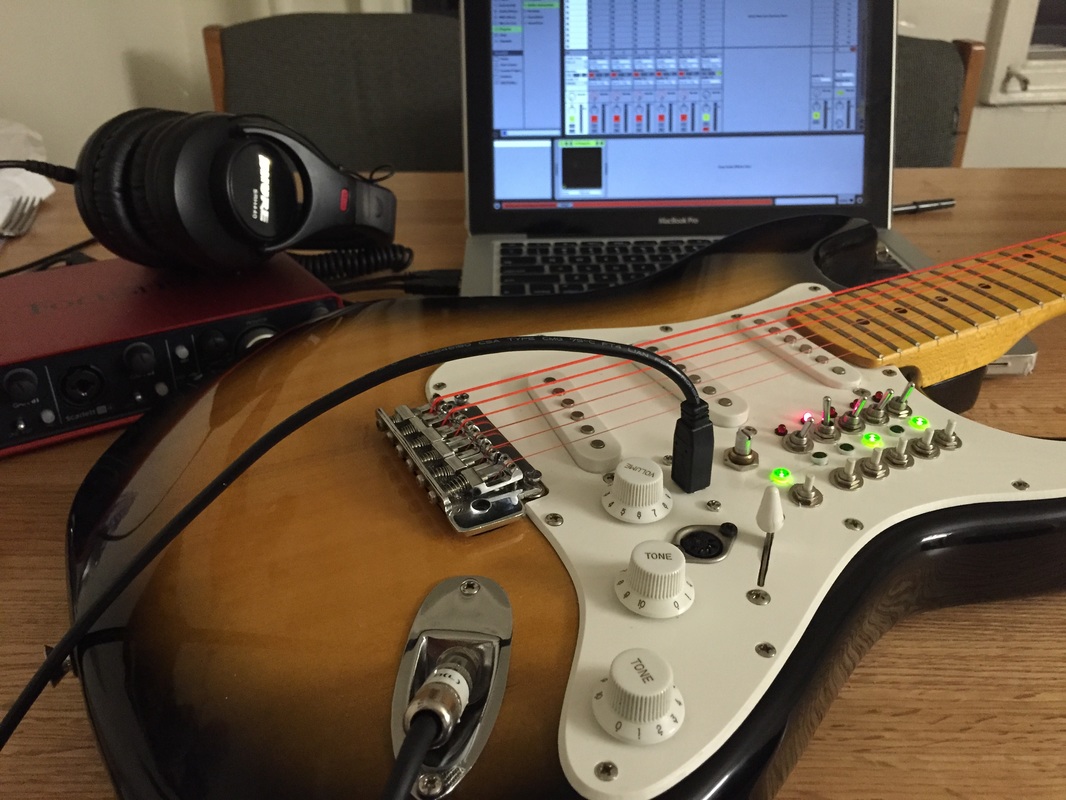
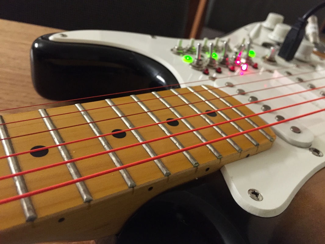
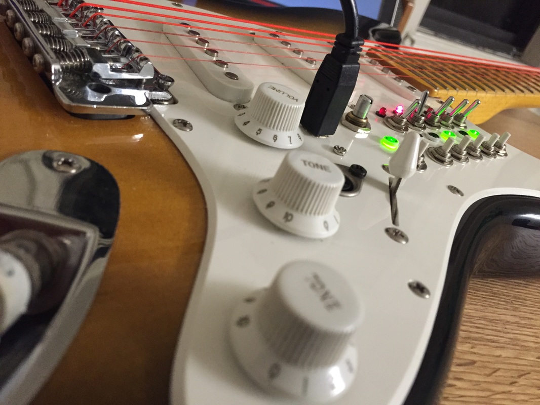
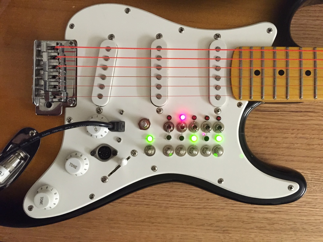
This is the culmination of my project. I was able to take pictures of most of the steps and the majority of the components so they are arranged relatively chronologically below with comments. 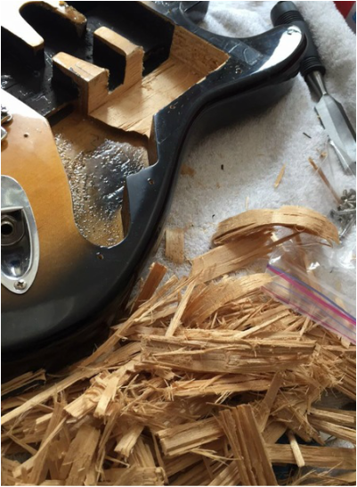 In order to fit the components under the pickguard, it was necessary to take out a lot of the material behind in that area of the guitar. With a rough outline, I used a 1 inch chisel and created the cavity pictured above and below. 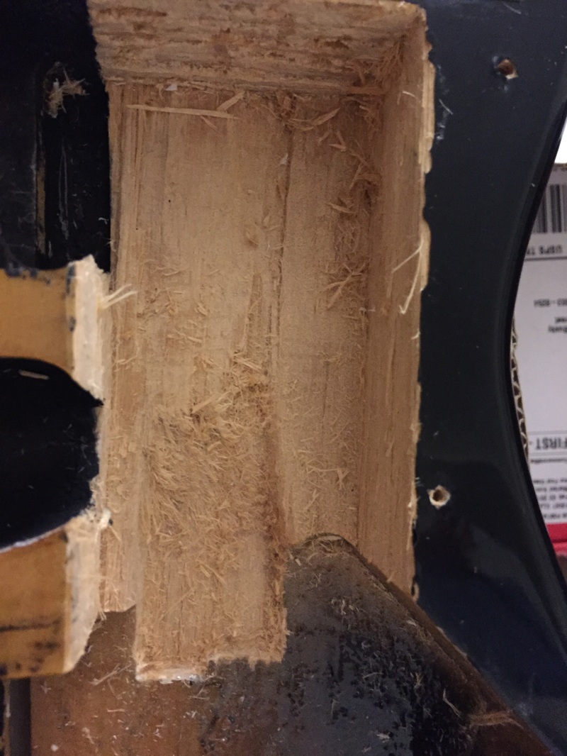 Cavity under the pickguard to fit the components. 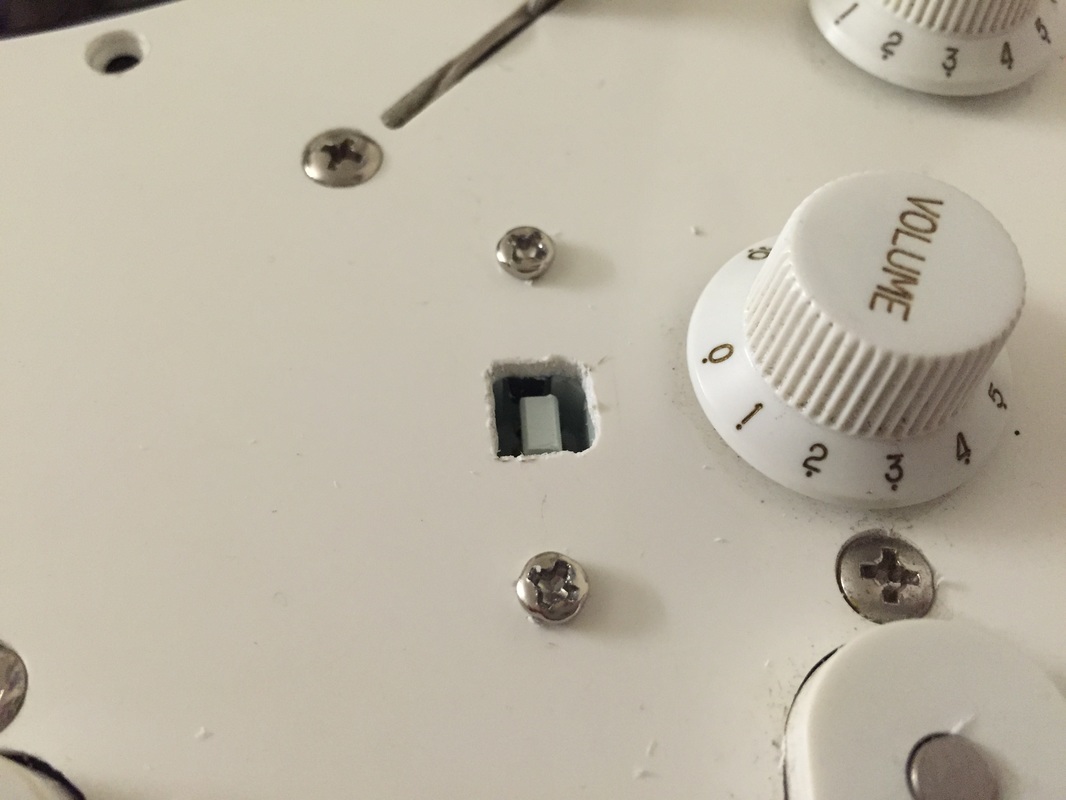 In order to connect the Teensy to my computer, I purchased a short panel mount USB Micro B to B cable and mounted the B end to the pickguard. This way, I can use a standard USB B to USB 3 cable that are readily available (USB B is used on standard home office equipment like printers and scanners) and not have to worry about breaking the Teensy inside with a cable connected directly to it. 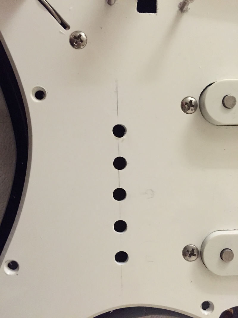 These are the first of the mounting holes for the LEDs. The LEDs I used are panel mount and are designed to clip into the hole upon insertion via 3 slight jogs in the casing. Not shown are the holes for the switches and buttons which were attached with standard nuts and washers. 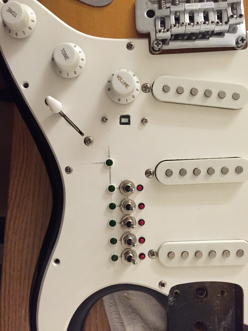 Coming together! All the switches and LEDs successfully mounted, only the buttons are left! 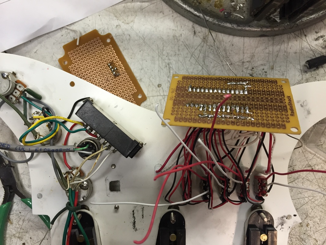 Here are the guts of the project. I used a small generic PCB (printed circuit board) and soldered a socket for the Teensy so that I can remove it in the future if I want to use it for other projects. Following my schematic, I laid out the board in a way that would compromise the layout of the Teensy's data pins with the ergonomic layout of my components. 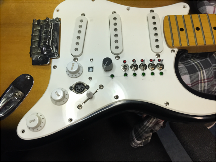 Almost done, except for the buttons again (these arrived later). You will notice there is a 5-pin MIDI connector mounted between two of the guitar's volume knobs. Initially this was going to serve as the audio tether to and from the computer. I made a 4-line cable with a MIDI connector on one end and a 1/4" TS split on the other to send the audio signal to and receive the summed loops from the computer so that the raw guitar signal and the loops could be sent out the normal output jack directly to an amp. Unfortunately, in practice, this introduced quite a bit of noise into the signal and created a feedback loop somewhere in the circuit. I had planned on simply splicing the two signals together at the output jack but this led to the above issues. To do it correctly would have required an analog summing circuit with an op amp which I did not have time to engineer so I decided to rely fully on the computer for audio routing and just send my guitar signal into my interface and take normal outputs from there. Above is a short video of the controller working alongside my Ableton session. 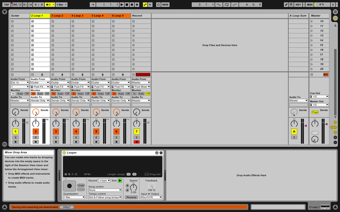 Above is my Ableton session for this project. From left to right I have an input track from which the raw guitar signal is monitored, 5 loop tracks which get signal from the input track and send to a single aux track to the left of the master track which sums all 5 and can modify the out-going level of all 5 loops together. Finally there is a record track to the right of the loops which takes signal from the master and records the entire performance in an audio file. The looping is done with Ableton's Looper plug-in, each of which is controlled via the MIDI signal from the Teensy. 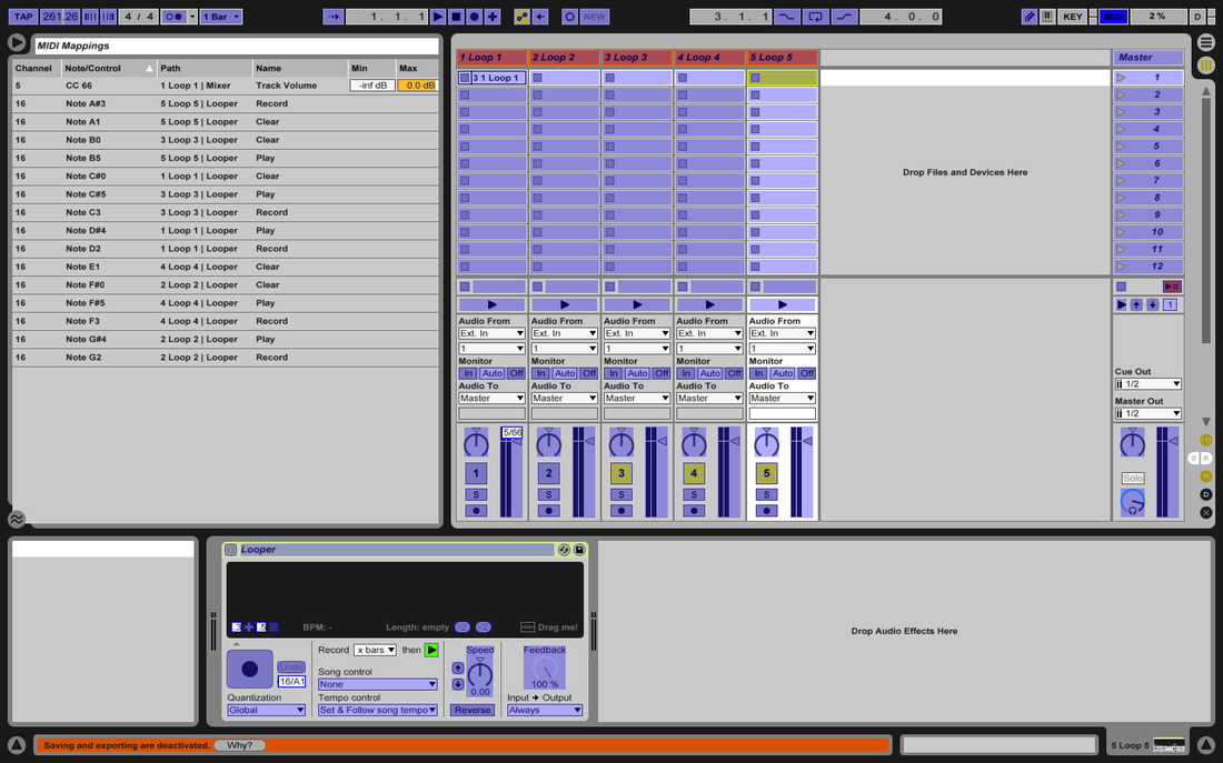 This is a screenshot of the MIDI mapping used in the project. Once I finished the physical interface, I was able to go through and quickly select a parameter and hit a button or switch to record the trigger and Ableton saved the trigger as such.
4 Comments
This week was a very successful week for my final project. I have finished coding and have run basic tests to ensure that both the circuit, code, and DAW will work in harmony. I was having issues with the reading of “not” states for my play/record switches but by drastically simplifying my code I was able to circumvent the inherent errors in my code (Page 1-2). I also modified my schematic and pin layout so that less calculation is necessary within the code to read and write the correct pins and so that it is less confusing overall (page 3). The circuit will be slightly less clean, but quality soldering and wiring will render this inconsequential. I have also come up with a plan for my PCB and have drawn it up with primitive symbols to represent external components (page 3). I also ordered a couple of extra parts including a socket so that I can easily mount and unmounts my Teensy within the guitar and a panel mount USB cable so that I can create a clean single run from the outside of the guitar into my computer (page 4). I also now plan on using a standard 5-pin MIDI connector and a custom cable to send and receive audio out and into the guitar from my interface. This will include a panel mount female MIDI connector on the guitar and a 4-wire cable with male 5-pin MIDI on one end and two 1⁄4” jacks on the other. Finally, I was able to map my MIDI controls within my Ableton Live session (page 4). All that is left to do is mount the circuit into my guitar and connect it to the guitar electronics. Using what I have learned in this week’s lab, I was able to finish my Arduino code and began testing it with simple jumper wires to emulate my switches and buttons before I mock up the project with the parts that I will eventually mount to my guitar. Attached is my code. Below is a picture of one of each of my parts. 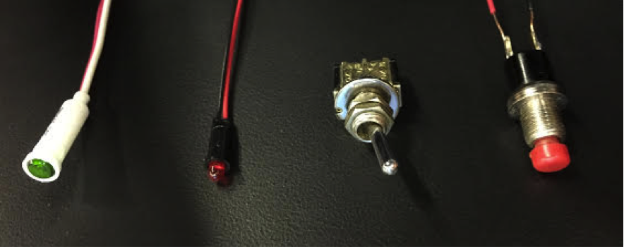 In order, a pushbutton, switch, and red and green LEDs. The LEDs are slightly different than those that I had initially found online and will require external load resistors so that they do not burn out. To allow easy mounting of this slightly additional circuitry, I will mount everything to perfboard and purchase a mounting block for my Teensy so that I can mount it on the board and house it in the guitar to keep everything streamlined. To allow for this, I will also purchase a panel mount USB port to mount near the 1⁄4” output jack of my guitar so that I can run a longer USB tether to my computer without it being snaked from the inside of the guitar. Pictoral representation of the user interface. The guitar is the guitar I will be using: 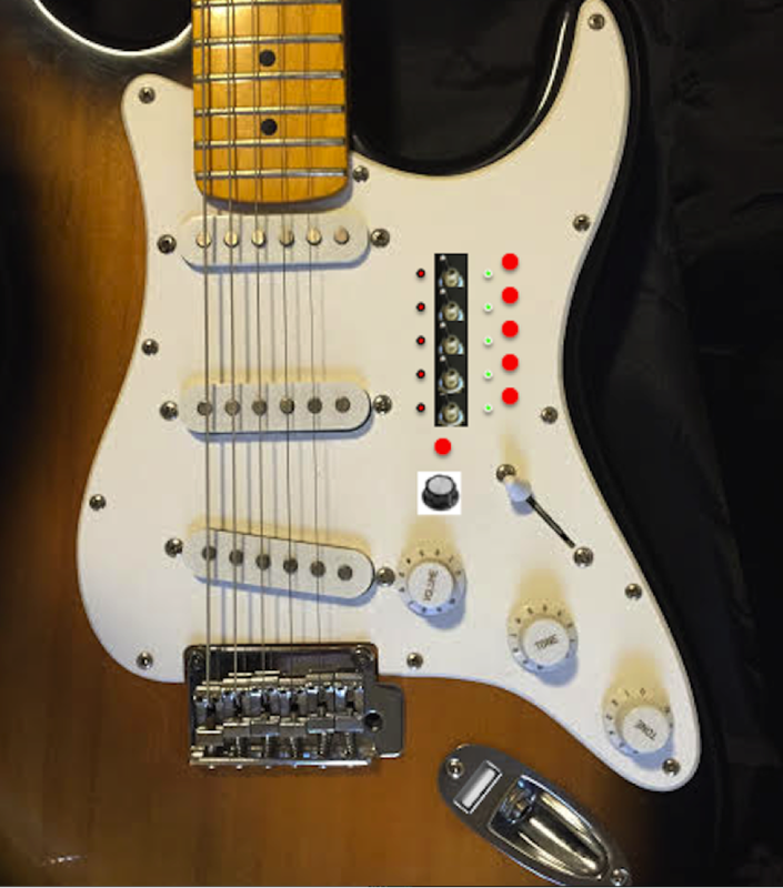 This week, I completed a large chunk of my Arduino code. I have completed the logic that will accept controls from the physical buttons and switches and that which will turn off and on the various on-board indicator lights. Currently, I only have to complete the MIDI interface between the code and the DAW. For this, I simply have to map my DAW controls to MIDI notes and write in these control commands within my code. Before I do this, I am going to have to work more with my user interface in order to ensure that it is intuitive for the user and contains all the control that I outlined in my proposal. This may require mocking up the physical project on my guitar, but I retrieved all of my necessary parts this weekend so this will not be an issue. I was able to source all of my parts from home including the panel-mount indicator LEDs in green and red. On the following pages is my code as it stands. Code to be inputted is inn double slashes as such: //_____(code)______// while comments are delineated as such // __(comment)_ Final Project Progress: So far I am slightly behind schedule with my final project. My DAW file is almost completely set up besides a few mapping nuances that I have to do more research to create (overall stop and play). I have to decide whether or not to perform these operations as duplicate maps in Live or use my Arduino code to set a single button to perform multiple tasks. The decision will be made on the grounds of speed and ease of application. I still have to work on writing my Arduino code but this will depend on how my Live session is structure and from where I am triggering certain actions. Again, here are my weekly goals: 1. Learn Ableton and build Loop session to accept teensy Midi and applicable controls and write Arduino code 2. Build prototype circuit on breadboard and begin debugging/troubleshooting 3. Finish debugging/troubleshooting and begin to finalize circuit on blank PCB 4. Mount circuit on PCB and mount project on the guitar. 5. Finalize aesthetics and practice performing Below is a screenshot of my Live session as it stands now with primitive Key mapping that will eventually be transferred to MIDI maps. 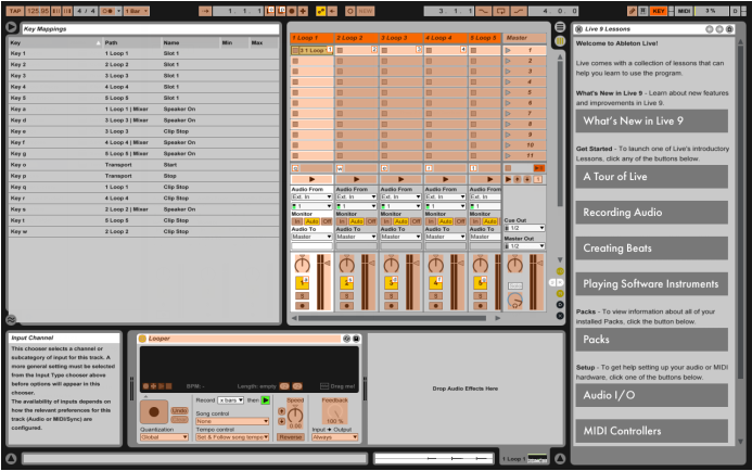 Project Proposal: Project Title: BE5 Multi Project Description: My project is an on-board 5-sample looper for the guitar. It will be built onto the interchangeable pickguard that most guitars utilize so that it can be easily dropped in to any guitar. It will include 5 switches to control the loops and an one switch to control all the loops together. Drawing: Schematic:  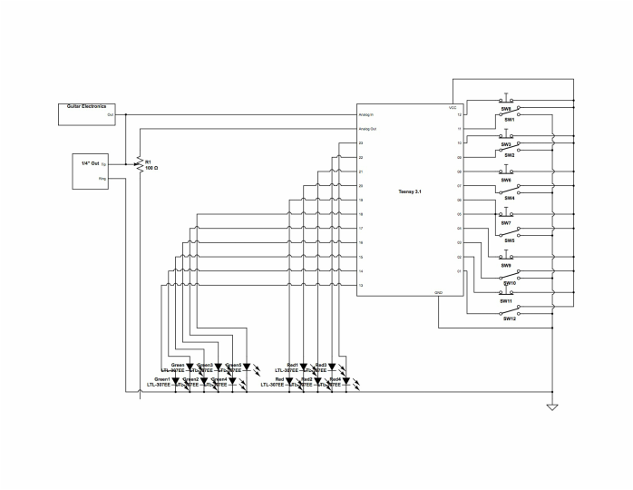 Pseudocode Outline: 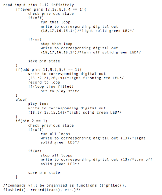 Parts List:
*(sourced from home, will retrieve on April 4th) Weekly Goals: 1. Learn Ableton and build Loop session to accept teensy Midi and applicable controls and write Arduino code 2. Build prototype circuit on breadboard and begin debugging/troubleshooting 3. Finish debugging/troubleshooting and begin to finalize circuit on blank PCB 4. Mount circuit on PCB and mount project on the guitar. 5. Finalize aesthetics and practice performing References and Previous Art: There is a similar device to mine called the Guitar Wing by Livid Instruments. I clips onto the bottom horn of the guitar and is a fully programmable MIDI controller tethered to the computer. My project has some of the functionality of this device but is more streamlined and built in to the instrument. In addition, my project has the potential to be DSP controlled and break its tether with the computer. Here is a link to Livid Instruments' website: http://shop.lividinstruments.com/guitar-wing/ In the same way, my project will be similar to the ET II final projects of Travis Fodor and Malakai Linden, but as with the Livid device, my project is currently only loop-focused and has potential to be powered by internal DSP rather than MIDI and computer connectivity. Having drawn up a sketch of my final project last week, this week I have complied a list of specifications for it.
5 samples
Onboard controls
Overall control
Integration
Aesthetics
I have gained a cohesive idea of my final project and a sketch is included below. It will be tethered to the computer for the sake of this lab and will include 5 SPDT switches to control the 5 loops to place them in Record, Play, or Stop modes. There will also be indicator lights to show the state of each loop and a single universal control button which will be able to stop and start all loops simultaneously. 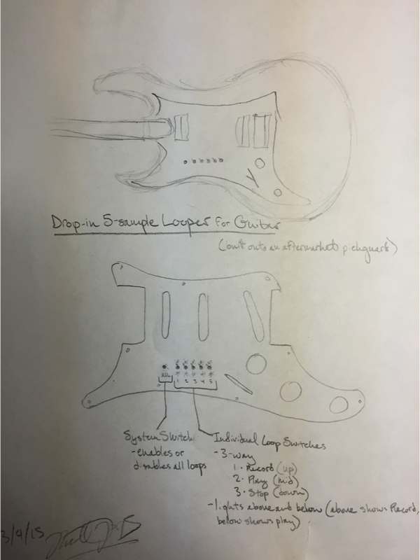 I am currently in a digital electronics class and for lab I have to create a performable final project utilizing the things I learned throughout the class. I had two original ideas; a multi-effect/looper pedal or an onboard effects processing unit. This week I have come up with a semi-new idea for my project. I have decided to combine my two previous ideas into an onboard loop/effects module for the guitar. For now I am going to go for at least 5 individually triggerable/recordable loops which would be trigger via bottons embedded in either the pick guard of an electric guitar or in the drop-in electronics on an acoustic-electric guitar. In the future, I see this becoming a drop-in module available for all guitars with optional additions that would add effects and onboard effects chain modification. This functionality would require that all processing be done onboard. Currently, I’m not sure if the Teensy board can handle that kind of processing or if it has enough memory to store the number of loops I’d like so for now, I’ll have to run it along with my computer with a DAW like Ableton. In the future, however, I’d like to purchase a raspberry pi board computer and use that in place of the full desktop/laptop machine and write my own simplified DAW/processor to handle my application. In addition, it is likely to be necessary, if I do not rely on a computer tether, that I will need to implement and additional memory system and interface in order to save and access audio samples for the looper. If this additional work means that I only implement the looper, that is fine and I can leave the onboard effects processing for later.
|
 RSS Feed