|
I have completed the distortion portion of my project. By setting the values of the potentiometers in my last circuit to fixed values and putting a voltage divider with a 3.3k resistor and a photoresistor bridging the input and the output with the output of the distortion circuit, the circuit now presents a clean signal when a large amount of light hits the photocell and a distorted sound when the light into the photocell is low. The way this works is, there is a fixed resistance set on the distorted side of the signal. On the clean side, the photoresistor, when at a low resistance, acts a a short circuit and bypasses the distorted side of the circuit. When the photoresistor is at a high resistance, it makes it more difficult for the clean signal to pass through and therefore allowing the distorted signal to pass through to the output. In order to get a very clean sound when I wanted to, I had to tune the resistances in the voltage divider so that I could get an undistorted sound and yet a full distorted signal on the other side. The 3.3k ohm resistor matched well with the resistance in the photocell and after many different trials with a range of resistances, I finally settled on that one. 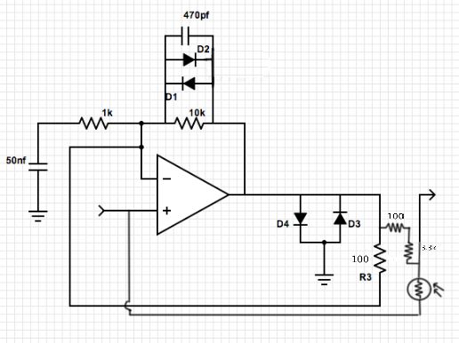
I also began the construction of the tremolo portion of my project. Using a 555 timer and a 358 op-amp, the circuit uses an LED to modulate the signal from my guitar. The 555 timer lights the LED at a regular time intervals and a photocell takes in that light signal as fluctuations in resistance which changes the filter on the signal. In my incarnation of the circuit, I will use a photocell in the circuit to vary the speed of the 555 timer and therefore the speed of the tremolo. 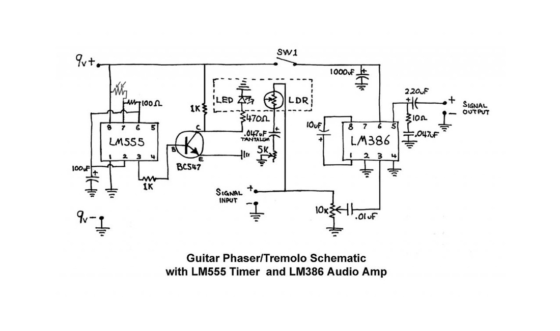
Below is an image of my project at its current stage. On the left side of the breadboard is the tremolo section and the right side contains the distortion circuit. the large grayish-green square of circuit board are my photocells. 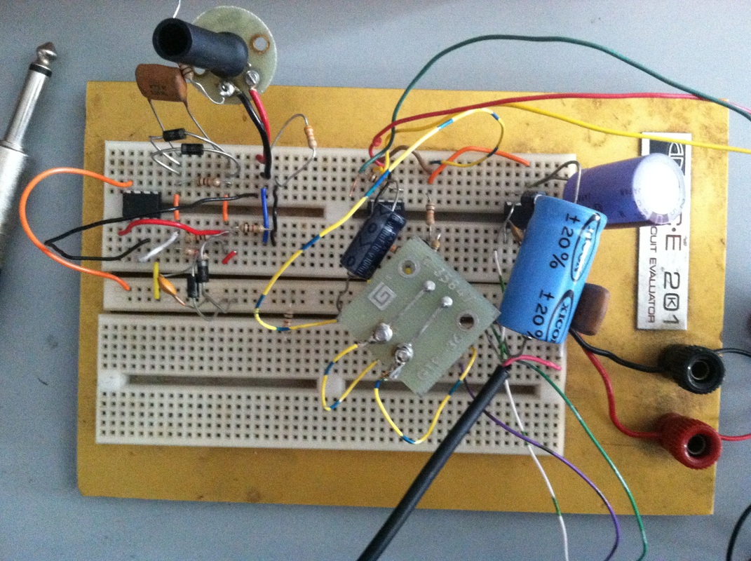
1 Comment
Last week, I began work on the distortion unit of my final project. I used the circuit below, based off of a schematic I found on the internet. The circuit uses a transistor and a few resistors to distort the signal you put into it. I placed a 10k ohm potentiometer across the circuit from the input to the output of the circuit with the wiper attached to the input of the speaker. This potentiometer was meant to fade between the wet and dry signal and essentially turn on and off the distortion circuit. Somehow, when the potentiometer was turned hard to one side, it caused the circuit to overdrive very hard and create an LFO-style sound from the circuit. Unfortunately, I am not entirely sure how the circuit created this sound and in general how the circuit works. 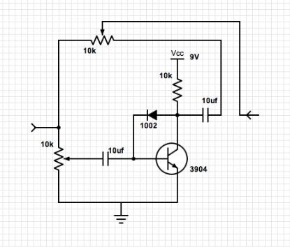
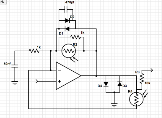
Because of the issues with my previous circuit, I decided to find a simpler circuit. I found the circuit below online as well. It is based on a network of diodes and resistors. Each set of parallel diodes only passes signal at certain frequencies and this causes a distortion effect, or rather, a clipping effect. For my final project, I instead to control my effects units using light. Previously, I had hit a roadblock because all of the photoresistors that I could find were only two sided. The applications I intend to use them in require them to act like potentiometers and these have three pins. I found a way to get around this issue by soldering a resistor to one of the legs of the photoresistor. This creates a voltage divider with one variable resistor. This way, the photoresistor acts very much like a potentiometer even though it only has two pins. Another trick I discovered is a way to change the taper of a photoresistor. By placing a resistor in parallel with the photoresistor, you can change the curve at which the the resistance changes and therefore get a more musically useful range. Below are the schematics and videos for the circuits described above. In addition, another advancement I made was to begin to integrate my guitar into the effect circuits. I unsoldered the output jack and routed the guitar signal through my breadboard before sending it back out the jack again and it works like a charm. As I further develop my project, I need to figure out a way to reverse my photoresistors so that when they have full light the signal is unaffected and when their light starts to get cut off the effect begins to come through. I also am going to introduce a switching system so that I can bypass all of my effects and not have to worry about relying on the state of the photoresistors to keep my signal clean when I want it. 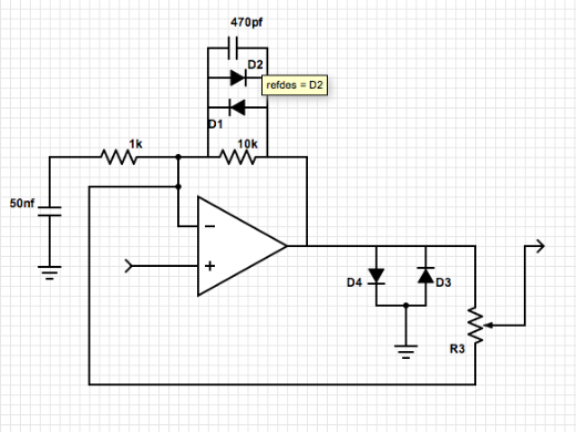
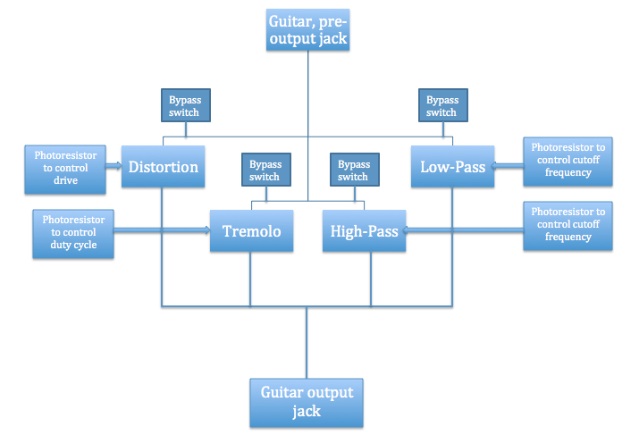
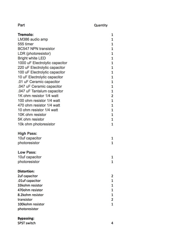
Experiments: This I created a simple audio amplifier using an LM358 op amp. While not built for audio, these little op amps will boost your signal even if they do provide quite a bit of loss in signal quality. The circuit that we used uses a resistor across the op amp to control the gain. In order to calculate the output voltage of the amplifier circuit, you can take the input voltage and multiply it by value of the resistor across the op amp divided by the value of the resistor before the op amp. In this case, the first resistor has a value of 2.2k ohms and the potentiometer over the op amp has a value of 10k ohms. Divide them out and you get about 4.54. This ratio is the amount of gain that the circuit can provide. The minimum gain for the circuit is obviously zero. When the potentiometer is set to a resistance of zero ohms, 0/2.2 will get a result of zero, and when you multiply the input voltage by a value of zero, that causes (mathematically) the output voltage to equal 0. Final Project: My final project is coming along well. Posted below are some of the developments. First is a drawing of the user interface, basically four photoresistors and four switches to turn the effects off and control them. Second is a flowchart for the project's signal chain starting at the end of the guitar's pre-installed circuitry and generally spliced in to the circuit before the output jack of the guitar. The third is a tentative bill of materials as I do not currently ha 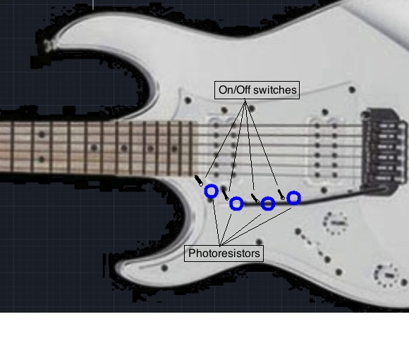
|
 RSS Feed