|
This week in lab I created an oscillator based on a 555 Timer chip. It produced a relatively wide range of frequencies in a rough squarewave pattern: EXPERIMENTS:
QUESTIONS:
FINAL PROJECT:
Here is a preliminary schematic of my final project. In future drafts, I will add an envelope filter and all variable resistors will be switched to photoresistors: 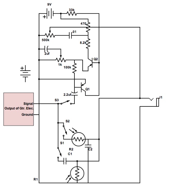
0 Comments
Experiments: Reverse Diode: This circuit bevels off the top of the sine wave. When you change the volume, it simply deepens the curve on the bottom. When frequency is brought up, the back side of the wave cuts off more steeply. Forward Diode: This circuit bevels off the bottom of the sine wave. Just as in the reverse diode circuit, when you change the volume, it simply deepens the curve on the bottom and when frequency is brought up, the back side of the wave cuts off more steeply. Forward Diode to Ground: This circuit cuts off the top of the wave sharply and widens it significantly. As you raise the volume, the effect becomes more and more present. As you change frequency, there is little to no change in the shape of the waveform. Reverse Diode to Ground: This circuit is the opposite of the forward diode to ground, cutting of the bottom of the wave and widening it. Similarly, as you raise the volume, the effect becomes more and more present and as you change frequency, there is little to no change in the shape of the waveform. Questions: A peak follower creates a decay by charging up and slowly draining a capacitor. It can be used to control any number of voltage controlled modules (VCOs, VCFs, etc). By simply adjusting the volume of the inputted signal, the shape of the curve can be made steeper or smoother depending on whether the volume was moved up or down. Using a peak follower, you could control the frequency of a VCO to make a tremolo effect or manipulate the cutoff frequency of a VCF to make an envelope. Below is a diagram of a circuit that would take the low frequencies of a drum machine, applies a smooth, almost square filter to the signal and then uses that signal to control the frequency of a voltage controlled oscillator. The initial resistor and then capacitor to ground form the filter to send through frequencies around 10-20Hz (see my previous post for more information about these types of filters), and then the following combination of reverse diode and reverse-biased diode to ground creates the filter. 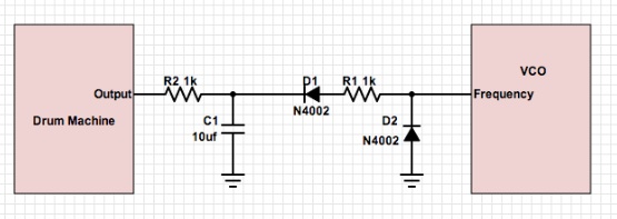 Final Project:
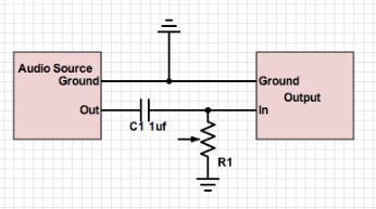
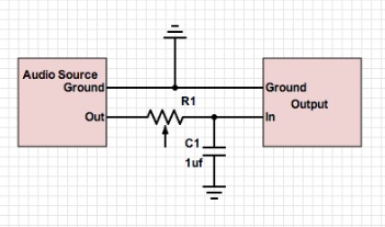
My final project is looking very plausible. I have been researching the potential for photoresistors in applications like mine. While the optimal device would be a proximity sensor, these parts cost upwards of $30 per unit so they are entirely out of contention. I have found that photoresistors are in a lot of things, from camera light sensors, to outdoor lights and night lights, these small, inexpensive devices are in many consumer electronics. I have many of these device at home not in use so I can take these apart and retrieve the LDRs (light-dependent resistors) from them. Unfortunately, I have hit one obstacle. Since the LDRs are essentially just variable resistors, I will have to do all the calculations to make sure that they are in the correct range for my application. For example, if I wanted to use my device as an extension of an existing effect pedal, I would have to be sure that my LDRs match the existing resistors in the device so that the circuit within the effect would not be put off balance. Because of this, there is a chance that I will not be able to find an LDR that works for my application and I will have to add on extra circuitry to make up for this. Also, because of this, it will be very hard to make the device compatible with a wide range of preexisting effects. Each effect has a different circuit and different value potentiometers. Because of these complications I am leaning towards an on board, or at least personally made set of filters that I will design to work well with the LDRs that are available. Experiments: The circuits pictured above are examples of high-pass and low-pass filters with adjustable cutoffs. Due to the reactance of a capacitor (Xc = 1/2pifC), when the frequency in a circuit is high, the reactance is low and inversely when frequency is low, reactance is reactance is high. Reactance is how much the current is impeded. When you have a capacitor going to ground and high frequencies are sent through the circuit, the capacitor is not stopping the signal from being sent out to ground so at high frequencies the output is very low because most of it is going to ground. When low frequencies are sent through the circuit, the reactance in the capacitor is high so it prevents the signal going to ground and therefore more can be sent to the output. Similarly, in a high pass filter, when the capacitor is in series in the signal chain, at low frequencies it simply prevents the signal from going through and at high frequencies provides little impedance to the flow of the current out to the output. The variable resistor simply acts as a voltage divider so you can change the voltage across the circuit and therefore change the frequency at which the circuit cuts off (the cutoff frequency). Questions: 1. When you have your RC circuit set as a highpass filter, there is a point at which the corner frequency goes above he range of human hearing. To improve this, you can adjust the value of the potentiometer that you're using so that at it's peak, it does not allow the corner frequency to rise above 20,000Hz. 2. When you have an RC circuit set as a lowpass filter, there is a point where the corner frequency goes below 20Hz and there is no change in sound beyond that point. To fix this, you can first change your potentiometer so that it is unable to reduce the corner frequency to less than 20Hz. 3. In order to make a filter with an even shaper cuttoff, you can put multiple filters in series. This way, you will essentially filter the filter or cutoff the cutoff. At the cutoff frequency you will sharpen that curve even further. Final Project: The project I have been researching is entirely analog. As it is essentially only a controller (an extension of the potentiometers on a stompbox), all the parts are entirely analog. If I were to include filters in the design, they would also be analog (distortion, envelopes, etc.). A typical proximity sensor is $50 plus so I will have to stick with the cheaper light sensors. If I can find a way to use them in reverse so that a high amount of light turns the pot off and as the level of light sensed goes down, the value of resistance goes down. Here is a preliminary sketch of my design: 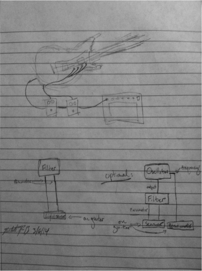 |
 RSS Feed