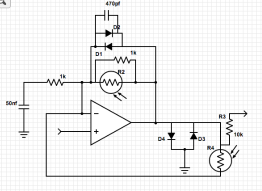
PRESENTING THE BE2-Vivid:My final project is an onboard effects unit for the electric guitar. It is a built-in device that uses light to control the amount and quality of the effects. Included in the unit is a distortion effect and a tremolo effect. You can control the amount of distortion and amount of tremolo by passing your hand and fingers in front of the sensors which are embedded in the guitar’s pickguard below the strings. This placement allows the user to use his/her strumming hand to manipulate the effects while still plucking/strumming the strings. The effects are built into the electronics of the guitar so the normal output jack can still be used. In the future, with larger funds, the electronics will all be housed in the body cavity under the pickguard. The flow of signal from the out of the pickups and guitar volume and tone pots is split and used as the input signal for each effect. In the distortion, the signal is run through an operational amplifier with a feedback loop set with diodes to clip the signal and provide a soft clipping to the signal peaks and a set of diodes post op-amp to ground to provide a harder clip on the peak of the signal waves. I placed my photoresistor in a voltage divider formation between the input signal and the output signal of the effect so that when the value of the photoresistor changes, it lets more of the clean signal through when there is a lot of light (low resistance is present), and lets more of the distorted signal through when there is little light (high resistance is present). This same blending technique is used on the tremolo unit to control the amount of tremolo signal in the output. The tremolo unit takes the same output signal from the original guitar electronics and passes it through a transistor whose base control voltage is controlled by a 555 timer. The fluctuating voltage shunts the signal to ground at the same speed as the timer and therefore creates the tremolo effect. One of the biggest problems I faced in my project was using a photoresistor instead of a potentiometer. One of the issues with these components is they only work in one direction. There is no way to switch the part to provide high resistance when there is a large amount of light and low resistance when there is little light. In my project, I wanted the off or low amount position to be when there is a large amount of light hitting the sensor so that when you are not manipulating the sensors the effects are off and they only come on when you put your hand over them. In order to overcome this, I discovered the voltage divider method with a constant resistor soldered to one of the photoresistor’s leads. This is not perfect, however, as the direction of resistance is still not always easy to keep track of and the taper of the makeshift “potentiometer” is very steep, not entirely suitable for all audio applications. The second issue of I faced in my project had to do with the tremolo unit. The LM555 timer introduces some inherent signal modulation to the power signal when it is plugged in to the battery power source. When the output signal is hooked up with the same power as the LM555, the modulation gets into the output signal and creates a click whenever the timer chip goes on and off. The only foreseeable solution to this issue is to completely isolate the timer with its own power source. The presence of the LED and photoresistor to modulate the signal in the original schematics I looked at is one step in the right direction, as there is no physical connection between the timer and audio portions of the circuits, but the power is still connected. I could use two batteries, but for my application this is a little excessive as my goal is to fit the entirely of the unit under the pickguard. Below is a video of the device in action! Here is the full schematic of my device: And finally, a recording of the device doing its thing!
0 Comments
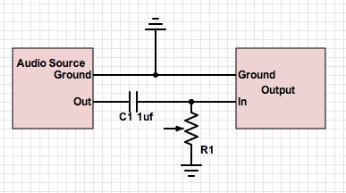
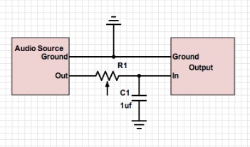
Work on my project is winding down. I currently have a fully functioning light-dependent distortion unit and a tremolo unit spliced together to the output of my guitar. I am still having issues with the tremolo. The circuit I am using utilizes an LM555 timer and when it is introduced to my circuit it creates a small click every time it turns on and off. Read through an oscilloscope, this modulation actually occurs through the power source as well, so to eliminate it, I will need to completely isolate the 555's power, which, for my application, is not entirely plausible. I also cannot use the photoresistor to vary the speed of the tremolo as there is no way to reverse the direction in which the resistance fluctuates due to light exposure. One idea I have is to use an oscillator and a JFET. This way, I could use a photoresistor to vary the frequency of the oscillator and feed the output into the base of the JFET so that the wave restricts the current flow through the JFET. When I splice the JFET ends into my circuit, it should sound relatively like a tremolo. I tried to use a summing amplifier to combine the signals from my different effects, however the quality of op amps that I have, the LM358s do not provide a very clean signal at all. In fact, when I hooked it up, the amplifier provided more distortion than my distortion unit. Simply splicing the outputs together does fine currently so that is what I will stick with. My biggest development from now till the end is putting my project onto my guitar. I will drill holes in the pickguard to mount my photocells and potentiometers. My eventual plan is to house the entire system within the electronics cavity of the guitar, however, I will need to route out the cavity more to accept more electronics and I also need to create a PCB for the system so that it will be solid instead of just on a breadboard. For now, I will just run the photoresistor leads out from under the pickguard and into a small box that I will mount on the body of the guitar which will house my breadboard. Below are video demonstrations of Distortion: and Tremolo: I have completed the distortion portion of my project. By setting the values of the potentiometers in my last circuit to fixed values and putting a voltage divider with a 3.3k resistor and a photoresistor bridging the input and the output with the output of the distortion circuit, the circuit now presents a clean signal when a large amount of light hits the photocell and a distorted sound when the light into the photocell is low. The way this works is, there is a fixed resistance set on the distorted side of the signal. On the clean side, the photoresistor, when at a low resistance, acts a a short circuit and bypasses the distorted side of the circuit. When the photoresistor is at a high resistance, it makes it more difficult for the clean signal to pass through and therefore allowing the distorted signal to pass through to the output. In order to get a very clean sound when I wanted to, I had to tune the resistances in the voltage divider so that I could get an undistorted sound and yet a full distorted signal on the other side. The 3.3k ohm resistor matched well with the resistance in the photocell and after many different trials with a range of resistances, I finally settled on that one. 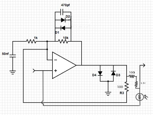
I also began the construction of the tremolo portion of my project. Using a 555 timer and a 358 op-amp, the circuit uses an LED to modulate the signal from my guitar. The 555 timer lights the LED at a regular time intervals and a photocell takes in that light signal as fluctuations in resistance which changes the filter on the signal. In my incarnation of the circuit, I will use a photocell in the circuit to vary the speed of the 555 timer and therefore the speed of the tremolo. 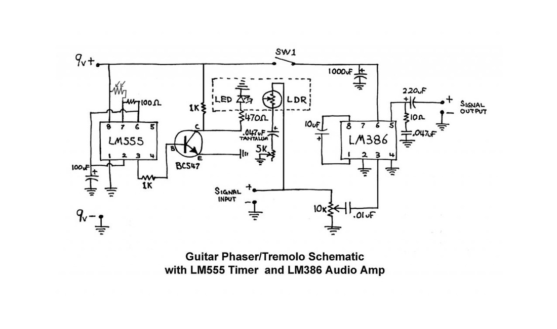
Below is an image of my project at its current stage. On the left side of the breadboard is the tremolo section and the right side contains the distortion circuit. the large grayish-green square of circuit board are my photocells. 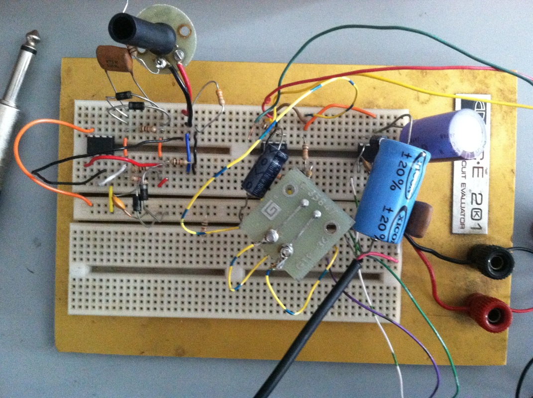
Last week, I began work on the distortion unit of my final project. I used the circuit below, based off of a schematic I found on the internet. The circuit uses a transistor and a few resistors to distort the signal you put into it. I placed a 10k ohm potentiometer across the circuit from the input to the output of the circuit with the wiper attached to the input of the speaker. This potentiometer was meant to fade between the wet and dry signal and essentially turn on and off the distortion circuit. Somehow, when the potentiometer was turned hard to one side, it caused the circuit to overdrive very hard and create an LFO-style sound from the circuit. Unfortunately, I am not entirely sure how the circuit created this sound and in general how the circuit works. 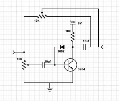
Because of the issues with my previous circuit, I decided to find a simpler circuit. I found the circuit below online as well. It is based on a network of diodes and resistors. Each set of parallel diodes only passes signal at certain frequencies and this causes a distortion effect, or rather, a clipping effect. For my final project, I instead to control my effects units using light. Previously, I had hit a roadblock because all of the photoresistors that I could find were only two sided. The applications I intend to use them in require them to act like potentiometers and these have three pins. I found a way to get around this issue by soldering a resistor to one of the legs of the photoresistor. This creates a voltage divider with one variable resistor. This way, the photoresistor acts very much like a potentiometer even though it only has two pins. Another trick I discovered is a way to change the taper of a photoresistor. By placing a resistor in parallel with the photoresistor, you can change the curve at which the the resistance changes and therefore get a more musically useful range. Below are the schematics and videos for the circuits described above. In addition, another advancement I made was to begin to integrate my guitar into the effect circuits. I unsoldered the output jack and routed the guitar signal through my breadboard before sending it back out the jack again and it works like a charm. As I further develop my project, I need to figure out a way to reverse my photoresistors so that when they have full light the signal is unaffected and when their light starts to get cut off the effect begins to come through. I also am going to introduce a switching system so that I can bypass all of my effects and not have to worry about relying on the state of the photoresistors to keep my signal clean when I want it. 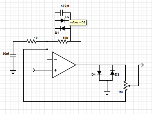
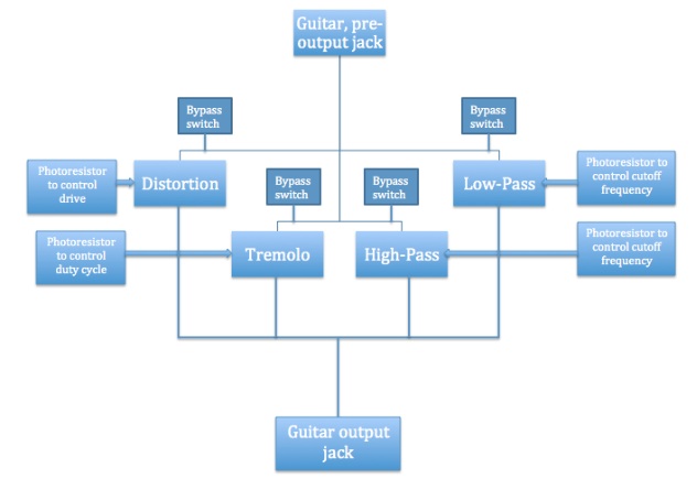
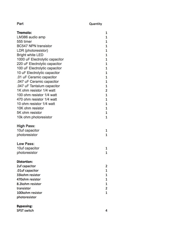
Experiments: This I created a simple audio amplifier using an LM358 op amp. While not built for audio, these little op amps will boost your signal even if they do provide quite a bit of loss in signal quality. The circuit that we used uses a resistor across the op amp to control the gain. In order to calculate the output voltage of the amplifier circuit, you can take the input voltage and multiply it by value of the resistor across the op amp divided by the value of the resistor before the op amp. In this case, the first resistor has a value of 2.2k ohms and the potentiometer over the op amp has a value of 10k ohms. Divide them out and you get about 4.54. This ratio is the amount of gain that the circuit can provide. The minimum gain for the circuit is obviously zero. When the potentiometer is set to a resistance of zero ohms, 0/2.2 will get a result of zero, and when you multiply the input voltage by a value of zero, that causes (mathematically) the output voltage to equal 0. Final Project: My final project is coming along well. Posted below are some of the developments. First is a drawing of the user interface, basically four photoresistors and four switches to turn the effects off and control them. Second is a flowchart for the project's signal chain starting at the end of the guitar's pre-installed circuitry and generally spliced in to the circuit before the output jack of the guitar. The third is a tentative bill of materials as I do not currently ha 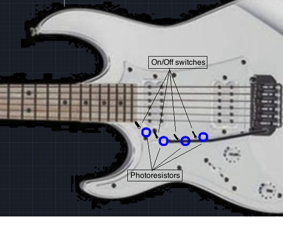
This week in lab I created an oscillator based on a 555 Timer chip. It produced a relatively wide range of frequencies in a rough squarewave pattern: EXPERIMENTS:
QUESTIONS:
FINAL PROJECT:
Here is a preliminary schematic of my final project. In future drafts, I will add an envelope filter and all variable resistors will be switched to photoresistors: 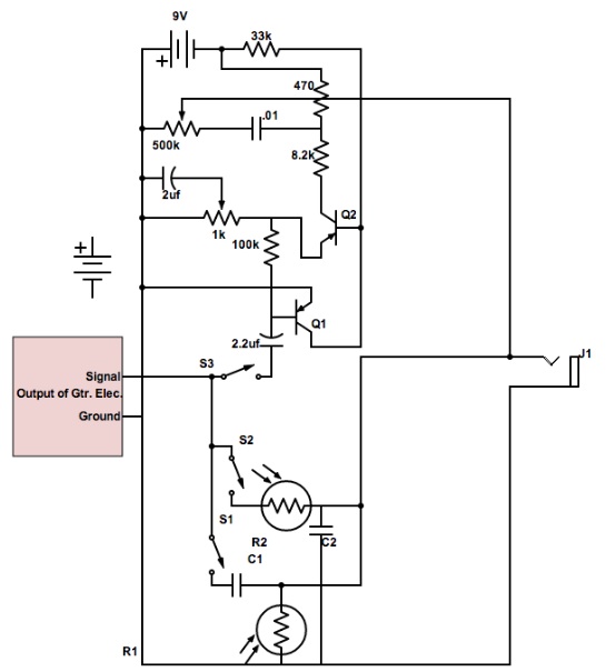
Experiments: Reverse Diode: This circuit bevels off the top of the sine wave. When you change the volume, it simply deepens the curve on the bottom. When frequency is brought up, the back side of the wave cuts off more steeply. Forward Diode: This circuit bevels off the bottom of the sine wave. Just as in the reverse diode circuit, when you change the volume, it simply deepens the curve on the bottom and when frequency is brought up, the back side of the wave cuts off more steeply. Forward Diode to Ground: This circuit cuts off the top of the wave sharply and widens it significantly. As you raise the volume, the effect becomes more and more present. As you change frequency, there is little to no change in the shape of the waveform. Reverse Diode to Ground: This circuit is the opposite of the forward diode to ground, cutting of the bottom of the wave and widening it. Similarly, as you raise the volume, the effect becomes more and more present and as you change frequency, there is little to no change in the shape of the waveform. Questions: A peak follower creates a decay by charging up and slowly draining a capacitor. It can be used to control any number of voltage controlled modules (VCOs, VCFs, etc). By simply adjusting the volume of the inputted signal, the shape of the curve can be made steeper or smoother depending on whether the volume was moved up or down. Using a peak follower, you could control the frequency of a VCO to make a tremolo effect or manipulate the cutoff frequency of a VCF to make an envelope. Below is a diagram of a circuit that would take the low frequencies of a drum machine, applies a smooth, almost square filter to the signal and then uses that signal to control the frequency of a voltage controlled oscillator. The initial resistor and then capacitor to ground form the filter to send through frequencies around 10-20Hz (see my previous post for more information about these types of filters), and then the following combination of reverse diode and reverse-biased diode to ground creates the filter. 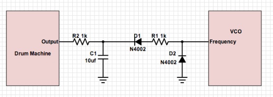 Final Project:
My final project is looking very plausible. I have been researching the potential for photoresistors in applications like mine. While the optimal device would be a proximity sensor, these parts cost upwards of $30 per unit so they are entirely out of contention. I have found that photoresistors are in a lot of things, from camera light sensors, to outdoor lights and night lights, these small, inexpensive devices are in many consumer electronics. I have many of these device at home not in use so I can take these apart and retrieve the LDRs (light-dependent resistors) from them. Unfortunately, I have hit one obstacle. Since the LDRs are essentially just variable resistors, I will have to do all the calculations to make sure that they are in the correct range for my application. For example, if I wanted to use my device as an extension of an existing effect pedal, I would have to be sure that my LDRs match the existing resistors in the device so that the circuit within the effect would not be put off balance. Because of this, there is a chance that I will not be able to find an LDR that works for my application and I will have to add on extra circuitry to make up for this. Also, because of this, it will be very hard to make the device compatible with a wide range of preexisting effects. Each effect has a different circuit and different value potentiometers. Because of these complications I am leaning towards an on board, or at least personally made set of filters that I will design to work well with the LDRs that are available. Experiments: The circuits pictured above are examples of high-pass and low-pass filters with adjustable cutoffs. Due to the reactance of a capacitor (Xc = 1/2pifC), when the frequency in a circuit is high, the reactance is low and inversely when frequency is low, reactance is reactance is high. Reactance is how much the current is impeded. When you have a capacitor going to ground and high frequencies are sent through the circuit, the capacitor is not stopping the signal from being sent out to ground so at high frequencies the output is very low because most of it is going to ground. When low frequencies are sent through the circuit, the reactance in the capacitor is high so it prevents the signal going to ground and therefore more can be sent to the output. Similarly, in a high pass filter, when the capacitor is in series in the signal chain, at low frequencies it simply prevents the signal from going through and at high frequencies provides little impedance to the flow of the current out to the output. The variable resistor simply acts as a voltage divider so you can change the voltage across the circuit and therefore change the frequency at which the circuit cuts off (the cutoff frequency). Questions: 1. When you have your RC circuit set as a highpass filter, there is a point at which the corner frequency goes above he range of human hearing. To improve this, you can adjust the value of the potentiometer that you're using so that at it's peak, it does not allow the corner frequency to rise above 20,000Hz. 2. When you have an RC circuit set as a lowpass filter, there is a point where the corner frequency goes below 20Hz and there is no change in sound beyond that point. To fix this, you can first change your potentiometer so that it is unable to reduce the corner frequency to less than 20Hz. 3. In order to make a filter with an even shaper cuttoff, you can put multiple filters in series. This way, you will essentially filter the filter or cutoff the cutoff. At the cutoff frequency you will sharpen that curve even further. Final Project: The project I have been researching is entirely analog. As it is essentially only a controller (an extension of the potentiometers on a stompbox), all the parts are entirely analog. If I were to include filters in the design, they would also be analog (distortion, envelopes, etc.). A typical proximity sensor is $50 plus so I will have to stick with the cheaper light sensors. If I can find a way to use them in reverse so that a high amount of light turns the pot off and as the level of light sensed goes down, the value of resistance goes down. Here is a preliminary sketch of my design: 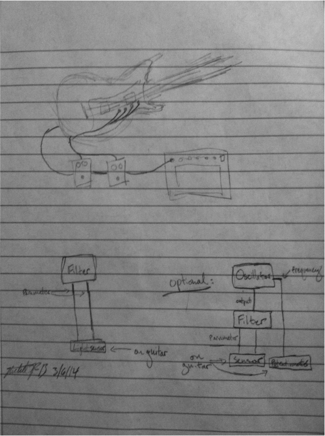 Experiment:
For this experiment I ran different frequencies through the circuit which is diagramed above. The circuit seems to have a treble roll-off effect as you can see in the graph of the amplitude response to change in frequency, as the frequency gets higher, the amplitude of the signal drops off. When you listen to white and pink noise through the circuit, the effect is the same, the higher frequencies are cut out while the lower frequencies stay constant when compared to the unprocessed signal. The capacitors I used in the circuit were what caused this amplitude drop at higher frequencies, but my results are actually quite strange as capacitors with lower values (like the 1uf ones in my circuit) in series usually act as high-pass filters instead of low-pass filters like the my results indicate. Final Project: In expanding upon my proximity guitar effect controller, I found that I could possibly make the device universal. It seems as though, what I am really designing is an extension for the potentiometers on normal instrument effects. If I could not create the necessary effects on my own, I can develop a connector that would go into a normal effects pedal so you could either plug in your on-board guitar controller via this connector (some type of multi-pin connector) or simply disconnect the device and use built-in knobs and switches on the effect. This development would allow users to use the device with any pedal but not limit themselves to one or two possible effects, but be able to plug into their entire pedalboard and at the same time maintain their pedals as traditional stompboxes. Another development I have made is attaching the device not to the guitar itself, but to the pickguard. On most guitars, the electronics are all bolted to the plastic pickguard not the actual wood of the body. By attaching my controller to the pickguard, the user can utilize my controller without having to do any major modifications to their instrument. You can buy replacement pickguards for $10 at retailers. The challenge with that design is that not all guitars have pickguards, then some modifications would need to be made to the guitar, but the concept would stay the same. The electronics would be mounted to a plastic sheet which will then be attached to the guitar. Questions:
1. In order to half the amplitude of the signal, you would have to use a voltage divider. By putting two resistors in series connected to ground and taking the output between the two resistors. 2.Capacitors changed the signal pattern by acting as filters. When you put a capacitor in series with the circuit, it acts as a high-pass filter, killing the low frequencies. When you hook it up as a bypass to ground, it acts as a low-pass filter, killing the high frequencies. When you use different values of capacitors, it will have an effect on the cutoff frequency. For example, when you are creating a high-pass filter, a higher value of capacitor will bring the cutoff frequency down. 3.The diode drastically affects the timbre of the sound by adding quite a bit of distortion. To put it into the circuit, I simply replaced the capacitors with the diodes. Final Project: 1. I would like to further discuss my second idea from last week, the photoresistor-controlled onboard guitar effect. Ideally, this would work in any ambient light situation, so in reality would use proximity sensors instead of photocells. The final product would be inset into the pick-guard with cells about the size of a finger (1/2" radius). I would have a few effects, filters, distortion, etc. that would have their controls manipulated by the sensors on the guitar. Most interesting would be to have a pitch bend or vibrato connected. Ideally, you would be able to switch between the different effects you are controlling easily on the guitar. With this, you can use a finger or two to control the effects and still play with your thumb and leftover fingers. The added expression from the effects makes up for the lack of notes available to play due to the lack of fingers available to pluck the strings. 2. Realistically, I will probably have to end up using photocells as proximity sensors are very expensive. To get around this, I could calibrate it so that sensitivity is low and when the cells are picking up the most light, the effect parameters are all the way at zero, so they aren't fluctuating full-out otherwise. Also, it would be very difficult and time-consuming to create a switching system that would allow you to control many different effects and aspects, this would probably require digital to be truly efficient. I will probably end up settling with one or two filters and manipulating two things on each. The easiest way to hook it up would to have the effects not on the guitar, but on a separate box. I can put together a guitar cable and the other wires necessary into a single cable and run it all through the input jack area on the guitar (using 1/4'' and multi-pin plugs). It would be easiest to take professional pedals and simply hotwire the pots to my photocells, but I will probably end up building my own to see how small I can get them to have the possibility of putting them on the guitar itself. Also, otherwise, the project seems a little too simple. |


 RSS Feed